100 Watt Led Driver Circuit Diagram
100 Watt Led Driver Circuit
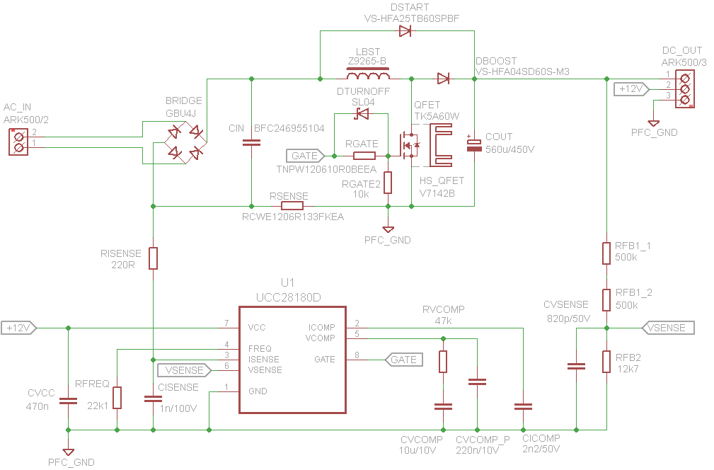
100w Led Driver Circuit Pfc Ucc28180 Ucc3813d 1 Electronics Projects Circuits

230v Led Driver Circuit Diagram Working And Applications Led Drivers Circuit Led
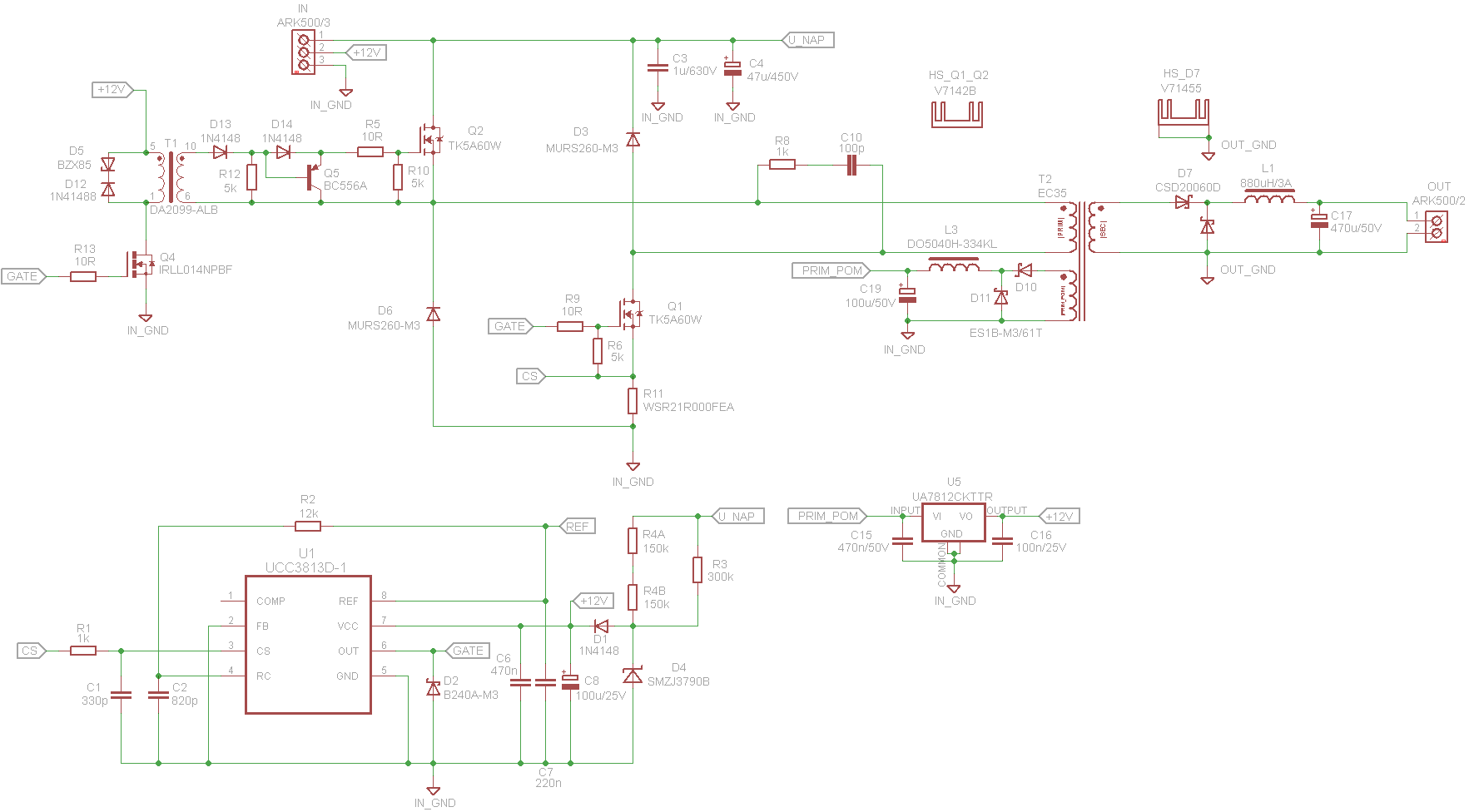
100w Led Driver Circuit Pfc Ucc28180 Ucc3813d 1 Electronics Projects Circuits
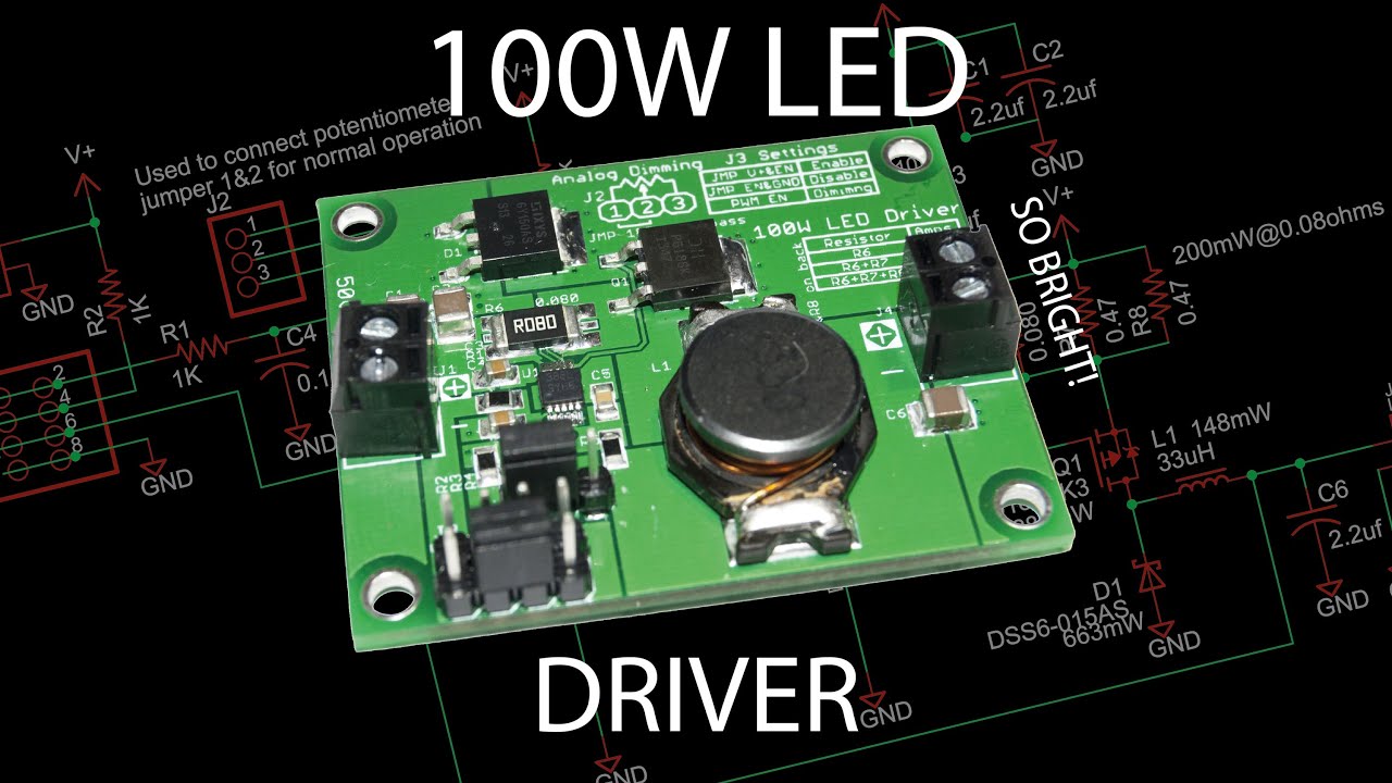
100w Buck Led Driver Board Using A Lm3409hv Youtube
Make A 100 Watt Led Floodlight Constant Current Driver Homemade Circuit Projects
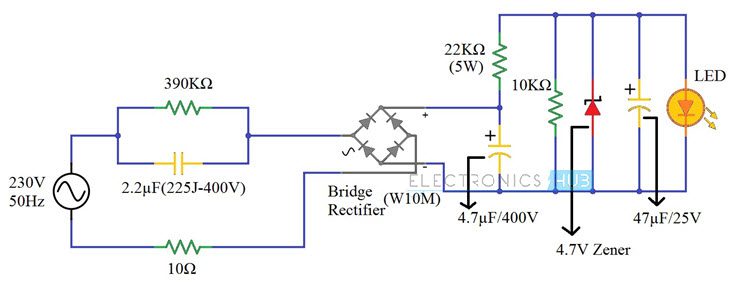
The main component is the x rated ac capacitor which can reduce the supply current to a suitable amount.
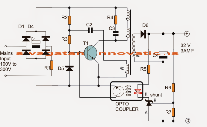
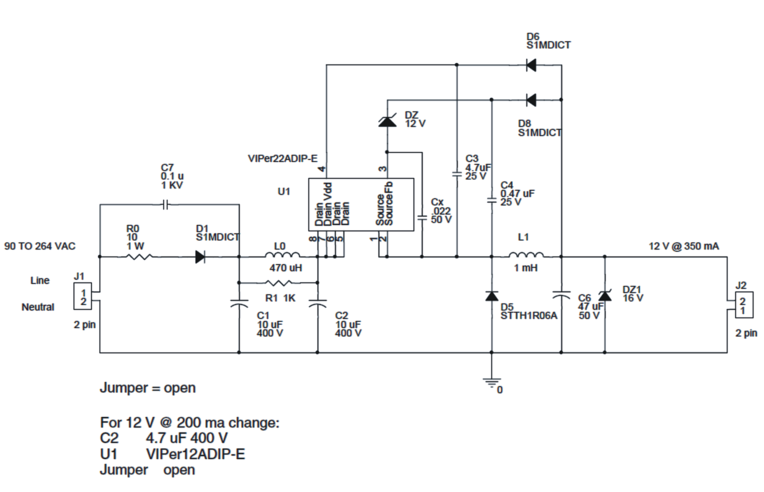
100 watt led driver circuit diagram. Led current in amps 1 25 r3 so for a current of 550ma set r3 to 2 2 ohms you ll need a power resistor usually r3 power in watts 1 56 r3 this circuit also has the drawback that the only way to use it with a micro controller or pwm is to turn the entire thing on and off with a power fet. The basic principle behind the 230v led driver circuit is transformer less power supply. So below i m writing an article on making of a high power led driver circuit. The input mains 220v or 120v ac is half wave repaired by d1 and c1.
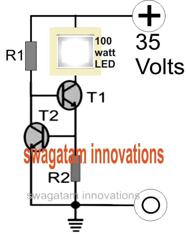
C1 together with the inductor l0 and c2 make up a pie filter network for cacelling emi disturbenaces. A simple two transistor powerful current limiter led driver circuit which can be used for converting the above discussed device into a 100 watt led flashlight or to be more accurate a floodlight is described below. These capacitors are connected line to line and are designed for high voltage ac circuits. Circuit 3 of simple led circuits leds in parallel the final circuit in the simple led circuits tutorial is leds in parallel.
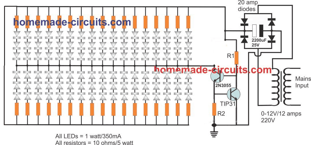
With 1 watt 350ma standard leds this would mean adding 310 3 3 93 leds in series that s close to 100nos. The circuit working of this 1 watt to 12watt led driver may be known as presented under. In this circuit we will try to connect three 5mm white leds in parallel and light them up using a 12v supply. The below device is able to run upto 5watt leds from the led supply line and 18watts of 12v led strips.
In the proposed 100 watt led bulb circuit we employ the same technique as discussed in the above sections. I got many requests to provide guide to build simple 230v to 1 3 5 watt led driver in response to my simple led driver diagram. And the only way to change the. As discussed if the input is 220v the load would need to be rated at 310v.

100w Led Driver For Dc 12v 24v Power Source Youtube

Simplest 100 Watt Led Bulb Circuit Homemade Circuit Projects Led Bulb Electronic Circuit Projects Led Bulb Diy
230v Led Driver Circuit Diagram Working And Applications
Make A 100 Watt Led Floodlight Constant Current Driver Homemade Circuit Projects
Rd L011 Reference Design General Led Driver Arrow Com

Power Integrations Unveils A19 Led Driver Reference Design Targeting 100 W Incandescent Bulb Replacements Led Professional Led Lighting Technology Application Magazine
5 Watt Led Driver Circuit Diagram

Led Driver Circuits Pdf
Lt3791 Typical Application Reference Design General Led Driver Arrow Com

Powering 100w 32v Leds Electrical Engineering Stack Exchange
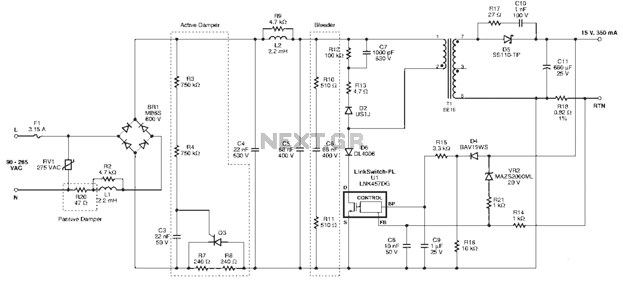
Linkswitch Pl Series Led Driver Circuit Under Led Circuits 57881 Next Gr

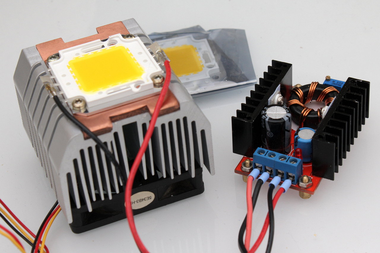
You May Also Like Using Aluminum Strip Heatsink For Hi Watt Leds Instead Of Pcb 0 6v To 6v 12v Boost Led Drivers Circuit Projects Electronic Circuit Projects
10 30 50 100w Led Application Driver Uc3843a 360customs
